

To see the task that need to be carried out on most boilers see the following article: Boiler Service
Intergas Boiler Service checklist for Natural Gas
- Ask client if there are any known issues with the boiler or the heating system.
- Check flue externally and internally for defects.
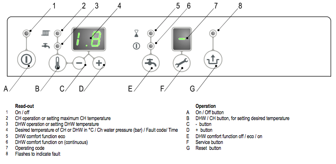
- Check the heat input on max mode. To activate the test program for maximum output by simultaneously pressing the buttons (Spanner) and '+' twice. A capital H appears in service display.
Checking flue gas at maximum power
- Switch the appliance off with the (Power) button. [-] will appear in service display.
- Remove the front panel by untightening the 2 screws.
- Remove the cap X of the flue gas sampling point on the adapter.
- Position the measuring probe or the flue gas analyser into the sampling point.
Important
- Ensure yourself that the analyser start up procedure has been finalized before placing the probe.
- The probe needs to close the sampling point fully to ensure an accurate measurement
- The end (tip) of the probe must be completely in the flue gasses (in the middle of the flue pipe)
- Switch the appliance on with the button.
- Activate the test program for maximum output by simultaneously pressing the (Spanner) buttons and (Plus) twice. A capital H appears in service display.
Important
- Make sure a capital H is shown in the display to ensure the appliance to run at maximum power.
- Wait until the reading of the flue gas analyser is stable (minimal 3 minutes)
- Note the measured value O2(H) or CO2(H)
- O2(H) = measured O2 value at maximum power
- CO2(H) = Measured CO2 value at maximum power
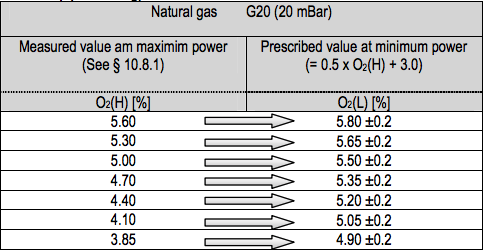
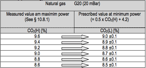
- Check if the measured value is in accordance with the data noted in table 2a or 2b
Limits O2(H) (Open Casing)
- Maximum value 5.60 %
- Minimum value 3.85 %
Limits CO2(H) at maximum power (open casing)
- Maximum value 9.6 %
- Minimum value 8.6 %
Checking flue gas at minimum output
- Activate the test program for maximum output by simultaneously pressing the buttons (spanner) and (minus). A capital L appears in service display.
- Wait until the reading of the analyser is stable (min. 3 minutes)
- Note the measured value O2(L) or CO2(L).
- O2(L) = is the measured value of O2 at minimum power
- CO2(L) = is the measured value of CO2 at minimum power
- Check if the measured value is in accordance to the data in table 3a or 3b
Limits O2(L) (Open Casing)
- Maximum O2 6.00%
- Minimum O2 O2(H)
Limits CO2(L) (Open Casing)
- Maximum CO2 CO2(H)
- Minimum CO2 8.4%
Correction gas air ratio on minimum power
Before the correction of the gas air ratio on minimum output the measurement of the maximum output must be completed. The measured O2 or CO2 value at maximum output is important for determining the correct value for the measurement at minimum output. See § 10.8.1 and § 10.8.2 for measuring at maximum output.
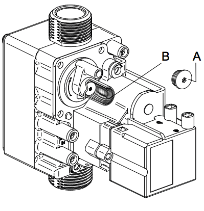
- Remove the cover cap (A) on the gas valve so setting screw B will become attainable.
- Activate the test program for minimum output by simultaneously pressing the (Spanner) buttons and (Minus) button. A capital L appears in service display.
- Wait until the reading of the analyser is stable (min. 3 minutes).
- Measure the O2(L) or CO2(L) value
- Set, using adjustment screw B de correct value for O2(L) or CO2(L). See table 5a or 5b for the correct value
- Choose the correct table (4a and 5a is for natural gas, 4b and 5b is for Propane).
- The value measured at maximum output as noted during the measurement on maximum output (CO2(H) or O2(H))
- Turning clockwise of the adjustment screw will raise the CO2 value and lower the O2 value. Turing anti clockwise will raise the O2 value and lower the CO2 value.
- Change the setting in small steps and wait until the reading is stable before continue.
Maintenance
The appliance and the installation should be checked and if necessary cleaned every year by a registered expert. For assembly and disassembly the following tools can be used:
- Cross head screwdriver
- Allen key 8 mm
- Fork spanner 30 mm
After servicing, complete the relevant Benchmark Service Record section located on page 51 of this document.
CAUTION: Work on gas carrying parts may only be carried out by an authorised installer. When the appliance has just been operating parts may be hot.
CAUTION: The integrated insolation and burner seal contain ceramic fibres.
Disassembly
- Switch the boiler off and isolate the boiler from the mains power.
- Close the gas tap.
- Open the display cover and turn the two screws on the left- and right-hand side of the display and remove the front panel.
- Wait until the appliance has cooled down.
- Unscrew the coupling nut at the base of the flue pipe anti-clockwise.
- Slide the flue pipe upwards (1) turning it anti-clockwise until the bottom of the pipe is above the condensate drain pan connection. Pull the bottom of the pipe forwards (2) and remove the pipe downwards (3) turning it anti-clockwise.
- Lift the condensate drain pan on the left-hand side from the connection to the condensate trap (4) and turn it to the right with the condensate trap connection over the edge of the base tray (5). Push the back of the condensate drain pan downward from the connection to the heat exchanger (6) and remove it from the appliance.
- Remove the connector from the fan and the ignition unit from the gas valve.
- Unscrew the coupling below the gas valve.
- Unscrew the shoulder bolts from the front cover and remove this complete with gas valve and fan to the front (NB: Ensure that the burner, insulation plate, gas valve, gas supply and fan do not get damaged).
Note: When the appliance is connected to a wall mounting jig with built-in expansion vessel a regular inspection of the expansion vessel pressure is advisable. Access to re-pressurise the expansion vessel is at the rear back of the vessel.
Cleaning
- Clean the heat exchanger from top to bottom with a plastic brush or compressed air.
- Clean the underside of the heat exchanger.
- Clean the condensate drain pan with water.
- Clean the condensate trap with water.
CAUTION: The boiler is equipped with a non-return valve (A), positioned above the fan. Ensure the non-return valve is repositioned correctly when replacing the fan.
Assembly
CAUTION: When fitting the various seals check for damage, hardening, tears or hairline tears and/or discoloration. Where necessary fit a new seal. Also check whether seals are still correctly positioned. Warranty will be void by not correctly replacing removed parts!
- Check if there is a small layer of ceramic grease on the contact surface between the shoulder bolt and the front plate
- Ensure that the seal around the front cover is installed correctly. Place the front cover on the heat exchanger and secure it using the socket head screws plus serrated lock washers. Tighten the shoulder bolts equally hand-tight (10–12 Nm), working crosswise.
- Fit the gas connection below the gas valve.
- Fit the connector to the fan and the ignition unit to the gas valve.
- Fit the condensate drain by sliding on to the exchanger outlet stump (1) with the condensate trap connection still in front of the base tray. Then turn it to the left (2) and push it downwards into the condensate trap connection (3). Make sure in doing this that the back of the condensate drain pan comes to rest on the lug at the back of the base tray (A).
- Fill the condensate trap with water and fit it to the connection below the condensate drain pan.
- Slide the flue pipe, turning it anti-clockwise, with the top around the flue adapter, into the top cover. Insert the bottom into the condensate drain pan and tighten the coupling nut clockwise.
- Open the gas tap and check the gas connections below the gas valve and on the mounting bracket for leakage.
- Check the CH and the water pipes for leakage.
- Switch on the mains power.
- Switch the appliance on with the key.
- Check the front cover, the fan connection on the front cover and the flue pipe components for leakage.
- Check the gas/air adjustment.
- Fit the casing, tighten the two screws left and right of the display and close the display cover.
- Check the heating and the hot water supply.
Combustion
During routine servicing, and after any maintenance or change of part of the combustion circuit the following must be checked:
- The integrity of the flue system and the flue seals, as described in § 8.5 and the British Standards codes of practices, specifically BS 5440.
- The integrity of the boiler combustion circuit and the relevant seals, as described in § 12.3.
- The operational (working) gas inlet pressure at maximum rate, as described in § 10.7.2.
- The combustion performance.